12-12-2023 - Mechanical Drawing - Representations [EN]-[IT]
~~~ La versione in italiano inizia subito dopo la versione in inglese ~~~
ENGLISH
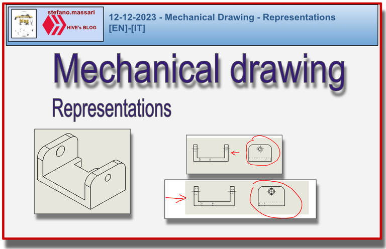
12-12-2023 - Mechanical Drawing - Representations [EN]-[IT]
Representations
Conventions have already been defined in the technical drawing to simplify and make clearer the representation of the details to be drawn.
Below are some examples.
Symmetrical objects can be drawn half or quarter.
If necessary, views can be produced according to observation directions different from the canonical ones.
When the full view is not necessary, a partial view can be produced.
Tips can be made. The parts that would be foreshortened in one of the views can be reversed for better reading.
The flat surfaces in view of a square, a truncated pyramid or a plane on the cylindrical body can be indicated with two fine continuous diagonal lines.
The intersections of filleted surfaces, also called fictitious edges, can be represented with a fine continuous line. One of the characteristics of these lines is precisely that they must not touch the contours, but stop slightly just before the contour.
One of the most particular things are the parts in front of the section plane. If it is really necessary, these parts can also be represented with a fine mixed line and two short strokes.
Repetitive elements can be represented even in a small quantity. However, it is always necessary to indicate the number and shape through the dimensioning. I have a note.
The views
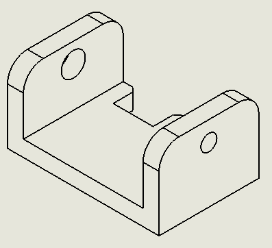
The views are of various types but the main ones are two: axonometric views and orthogonal views.
Below is an example of an isometric axonometric view
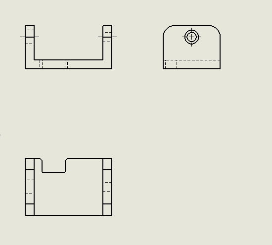
Below is an orthogonal projection
Regarding orthogonal projections, it is important to say that they can be represented with two main methods.
The two methods are the first dihedral and the third dihedral.
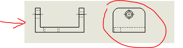
Below is an example of a representation with the first dihedral method.
It is essentially the same as the image above.
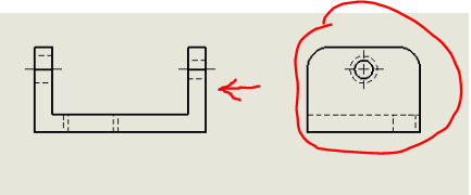
Below is an example of orthogonal projection views with the third dihedral method.
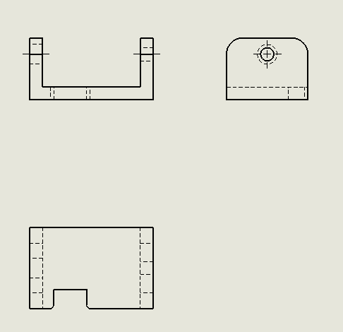
The first dihedral method is widespread in Europe, while the third dihedral method is also called the American method as it is widespread in America.
In the first dihedral method the objects are located between the observer and the projection plane, while in the third dihedral method the projection plane is located between the observer and the object.
Graphic explanation of the first dihedral.
Graphic explanation of the third dihedral.
Conclusions
In Europe, orthogonal views are represented with the first dihedral method, while in America they are represented with the third dihedral method.
![]()
ITALIAN
12-12-2023 - Disegno Meccanico - Rappresentazioni [EN]-[IT]
Rappresentazioni
Nel disegno tecnico sono già state definite le convenzioni per semplificare e rendere più chiara la rappresentazione dei particolari da disegnare.
Qui di seguito alcuni esempi.
Gli oggetti simmetrici possono essere disegnati per metà o un quarto.
Se sono necessarie si possono produrre viste secondo direzioni di osservazione differente da quelle canoniche.
Quando la vista completa non è necessaria si può produrre una vista parziale.
Si possono effettuare ribaltamenti. Le parti che risulterebbero di scorcio in una delle viste possono essere ribaltate per una migliore lettura.
Le superfici piane in vista di un quadrato, di un tronco di piramide o di un piano sul corpo cilindrico, possono essere indicate con due linee diagonali continue fini.
Le intersezioni di superfici raccordate, anche chiamate spigoli fittizi, possono essere rappresentate con linea continua fine. Una delle caratteristiche di queste linee è proprio quella che non devono toccare i contorni, ma si fermano leggermente poco prima del contorno.
Una delle cose più particolari sono le parti anteriori al piano di sezione. Se è proprio necessario si possono rappresentare anche queste parti con una linea mista fine e due tratti brevi.
Gli elementi ripetitivi possono essere rappresentati anche in una piccola quantità. Però è sempre necessario indicare il numero e forma mediante la quotatura ho una nota.
Le viste
Le viste sono di vari tipi ma le principali sono due: viste assonometriche e viste ortogonali.
Qui di seguito un esempio di vista assonometrica isometrica
Qui di seguito una proiezione ortogonale
Per quanto riguarda l proiezioni ortogonali è importante dire che si possono rappresentare con due metodi principali.
I due metodi sono quello del primo diedro e quello del terzo diedro.
Qui di seguito un esempio di una rappresentazione con il metodo del primo diedro.
Sostanzialmente è uguale all'immagine riportata prima.
Qui di seguito un esempio di viste in proiezione ortogonale con il metodo del terzo diedro.
Il metodo del primo diedro è diffuso in Europa, mentre il metodo del terzo diedro è chiamato anche metodo americano in quanto diffuso in America.
Nel metodo del primo diedro gli oggetti si trovano tra l'osservatore e il piano di proiezione, mentre nel metodo del terzo diedro il piano di proiezione si trova tra l'osservatore e l'oggetto.
Spiegazione grafica del primo diedro.
Spiegazione grafica del terzo diedro.
Conclusioni
In Europa le viste ortogonali vengono rappresentate con il metodo del primo diedro, mentre in America vengono rappresentate con il metodo del terzo diedro.
THE END
Till now I still find it difficult to draw orthographic projection
In my opinion they are the easiest representations and in any case with the new three-dimensional modeling software, there is no longer any need to know how to construct orthogonal views, the software already does it.
Is there always supposed to be a measurement of each drawing or it is just possible to draw anything with any measurement?
You can draw anything, but not at any scale. A list of the drawing scales to be used has also been made. For example, it is not allowed to draw an object in 1:13 scale, but in 1:10 scale it is.
I didn't know this, I'm referring to your conclusion.
I wish you a happy night
Sai che non so se in America Latina per i disegni tecnici si usa la rappresentazione americana (terzo diedro) o europea (primo diedro)? Prova a chiedere ai tuoi clienti o fornitori... sempre che tu abbia tempo