09-10-2023 - Mechanical Drawing - Representation conventions[EN]-[IT]
~~~ La versione in italiano inizia subito dopo la versione in inglese ~~~
ENGLISH
In technical mechanical drawing there are particular representation conventions. In this post we will see some of them.
Representation conventions
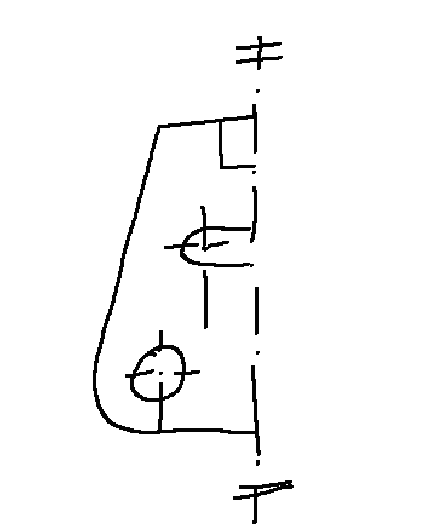
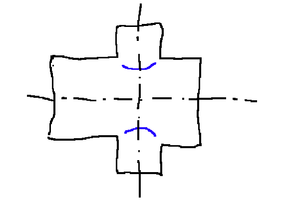
Symmetrical objects
These objects can be partially represented. There must be two short, parallel sections in the axes of symmetry
see example below
special views
Sometimes it may be necessary to show views different from the canonical ones, as in the example below. The particular views are identified with an arrow and a letter.
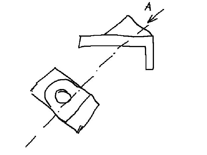
partial views
These views are useful for showing a detail if the full view is not needed and focusing attention on just one detail of the drawing. Example below.
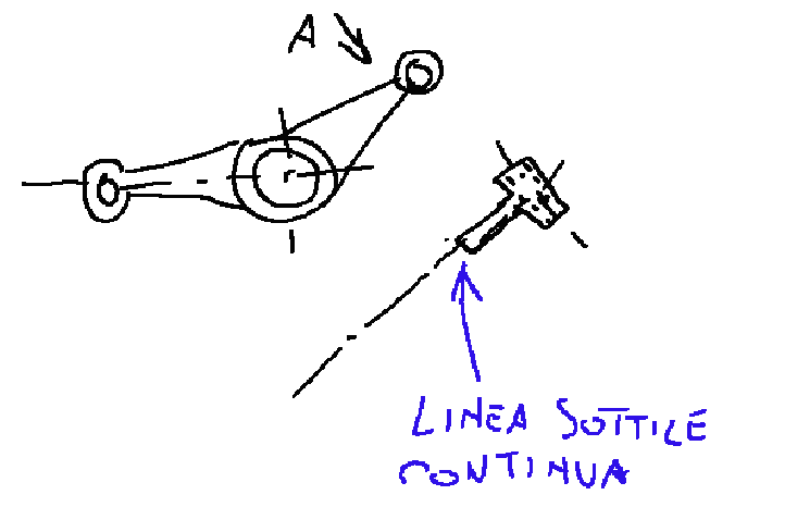
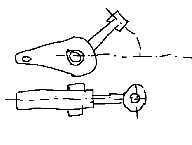
Reversals
Sometimes it may be necessary to carry out reversals because some pieces would be represented at an angle and this may not give the information we want to convey. The feature points that are flipped must be marked with thin trajectories and arcs.
example of tipping shown below.
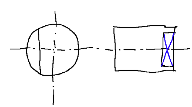
Flat surfaces on cylinder
Flat surfaces represented on a cylinder can be marked with two fine diagonal lines
See example below
Dummy edges
The intersections of connected surfaces can be represented with a fine line without it touching the contours.
Image shown below
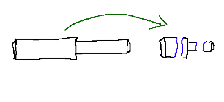
views interrupted
When representing very long details, the interrupted views method can be used. Instead of representing the piece in its entire length, it can be broken up, creating a partial view marked by fine continuous regular lines or zigzags.
Example below
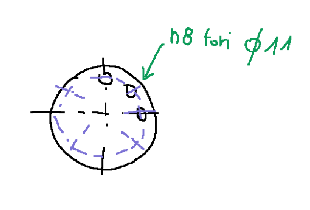
Repetitive elements
Repetitive elements can be omitted, but the number and shape must always be indicated by dimensioning or a note.
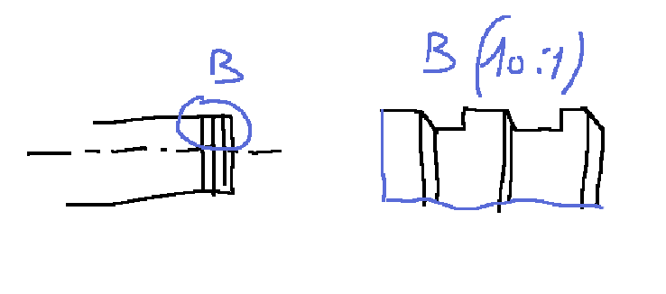
Enlarged scale representations
These representations are like when there are small processes on a large piece
The drawing of the enlarged scale must be surrounded by a continuous fine line, identified by a letter and with the specification of the scale
example below
The regulations relating to these indications are as follows
UNI EN ISO 128-24
Technical drawings - General principles of representation - Part 24: Lines used in mechanical and industrial engineering drawings
UNI EN ISO 128-30
Technical drawings - General principles of representation - Part 30: Fundamental conventions for views
UNI EN ISO 128-34
Technical drawings - General principles of representation - Part 34: Views in mechanical and industrial engineering drawings
![]()
ITALIAN
Nel disegno tecnico meccanico esistono delle convenzioni particolari di rappresentazione. In questo post ne vedremo alcune.
Convenzioni di rappresentazione
Oggetti simmetrici
Questi oggetti possono essere rappresentati parzialmente. Negli assi di simmetria dovranno essere presenti due tratti corti e paralleli
vedi esempio qui sotto
viste particolari
A volte potrebbe essere necessario mostrare viste differenti da quelle canoniche, come nell'esempio qui sotto riportato. Le vista particolari si identificano con una freccia e una lettera.
viste parziali
Queste viste sono utili per mostrare un particolare se non è necessaria la vista completa e concentrare l'attenzione solo su un particolare del disegno. Esempio qui sotto.
Ribaltamenti
Alcune volte potrebbe essere necessario effettuare dei ribaltamenti perché alcuni pezzi verrebbero rappresentati di scorcio e questo potrebbe non dare l'informazione che vogliamo trasmettere. I punti caratteristici che vengono ribaltati devono essere contrassegnati con traiettorie ed archi sottili.
esempio di ribaltamento riportato qui sotto.
Superfici piane su cilindro
Le superfici piane rappresentate su un cilindro possono essere contrassegnate con due linee diagonali fini
Vedi esempio qui sotto
Spigoli fittizi
Le intersezioni di superfici raccordate possono essere rappresentate con una linea fine senza che questa vada a toccare i contorni.
Immagine riportata qui sotto
viste interrotte
Quando si rappresentano particolari molto lunghi, si può usare il metodo delle viste interrotte. Anziché rappresentare il pezzo in tutta la sua lunghezza questo si può spezzare creando una vista parziale contrassegnata da linee fini regolari continue o zig-zag.
Esempio qui sotto
Elementi ripetitivi
Gli elementi ripetitivi possono essere omessi, ma è necessario sempre indicare numero e forma mediante la quotatura o una nota.
Rappresentazioni in scala ingrandita
Queste rappresentazioni sono come quando ci sono piccole lavorazioni su un pezzo di grandi dimensioni
Il disegno della scala ingrandita deve essere contornato da una linea fine continua, identificato da una lettera e con la specifica della scala
esempio qui sotto
Le normative relative a queste indicazioni sono le seguenti
UNI EN ISO 128-24
Disegni tecnici - Principi generali di rappresentazione - Parte 24: Linee utilizzate nei disegni di meccanica e di ingegneria industriale
UNI EN ISO 128-30
Disegni tecnici - Principi generali di rappresentazione - Parte 30: Convenzioni fondamentali per le viste
UNI EN ISO 128-34
Disegni tecnici - Principi generali di rappresentazione - Parte 34: Viste nei disegni di meccanica ed ingegneria industriale
THE END
But how can this kind of drawing be used in engineering or what can it help an engineer for?
This method is internationally recognized, so it can be understood by any engineer or design engineer in the world
@tipu curate 2 ✌
Upvoted 👌 (Mana: 33/53) Liquid rewards.
Grazie per il tipu. Provo a fare un po’ di post tecnici per diminuire il numero dei miei followers (battuta alla Roby)
Disegno tecnico, lo spieghi bene
Grazie LU, ho disegnato pezzi meccanici, per un periodo della mia vita è stato il mio lavoro. Grazie per il tuo supporto. !LUV
@lupega, @stefano.massari(2/5) sent LUV. | connect | community | HiveWiki | NFT | <>< daily
! help(no space) to get help on Hive. Info