04-10-2023 - Mechanical Drawing - prospective projections [EN]-[IT]
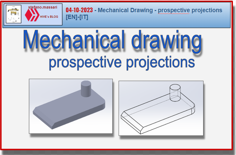
The screenshots are of a mechanical part that I designed myself
~~~ La versione in italiano inizia subito dopo la versione in inglese ~~~
ENGLISH
In technical mechanical drawing, perspective projections help to better understand the shape of a complicated object or a set of pieces assembled together.
Perspective Projections
Projection Methods
The central perspective projection can be constructed with 1 point, 2 points or 3.
In 1-point perspective all lines perpendicular to the pressure plane converge at the vanishing point coinciding with the principal point.
In 2-point perspective all the horizontal lines of a representation converge at their respective vanishing points on the horizon line.
In 3-point perspective if the projection plane is inclined towards the projection center, the vanishing point of the vertical lines is located below the horizon line.
The reference standard for perspective representations is the following.
UNI EN ISO 5456‐4: Technical Drawings. Projection methods. Perspective representations
Elementary shape elements
The elements of elementary shape can be one-dimensional such as points and axes, they can be two-dimensional such as circumferences and flat surfaces, or they can be three-dimensional such as cylindrical and conical surfaces
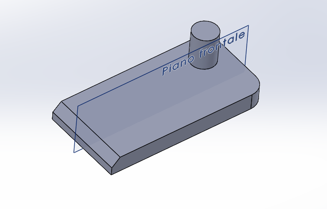
The main elements of elementary form are: axes and planes of symmetry, circumferences, flat surfaces, cylindrical and conical surfaces.
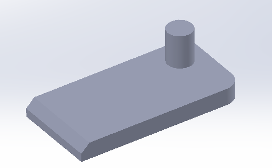
Below is an example of a symmetry plane.
Perspective and axonometric views have the advantage of immediately perceiving the three-dimensionality of the object.
Very often they are used in the construction and architecture sectors.
While in the field of mechanics, axonometric views are quite useful for representing assemblies or exploded views of mechanical groups
CAD perspective views
In CAD3D systems, axonometric views can be represented in 3 ways:
– Wire frames
– Hidden edges
– Shading
Below are the graphic examples:
Wire frames
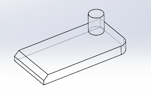
Hidden edges
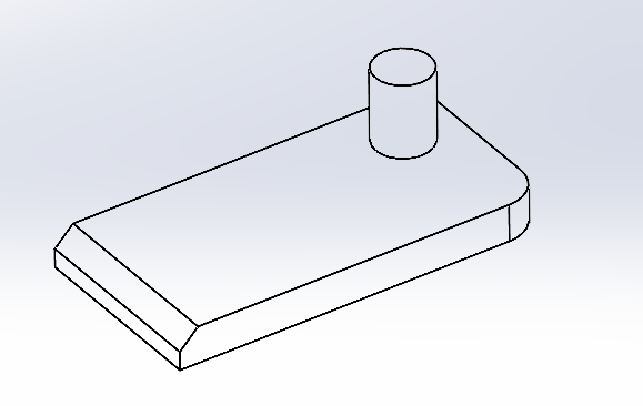
Shading
![]()
ITALIAN
Nel disegno tecnico meccanico le proiezioni prospettiche aiutano a comprendere meglio la forma di un oggetto complicato oppure un insieme di pezzi assemblati tra loro.
Proiezioni Prospettiche
Metodi di proiezione
La proiezione centrale prospettica si può costruire con 1 punto, con 2 punti oppure con 3.
Nella prospettiva ad 1 punto tutte le linee perpendicolari al piano di pressione convergono nel punto di fuga coincidente con il punto principale.
Nella prospettiva a 2 punti tutte le linee orizzontali di una rappresentazione convergono nei rispettivi punti di fuga sulla linea d’orizzonte.
Nella prospettiva a 3 punti se il piano di proiezione è inclinato verso il centro di proiezione, il punto di fuga delle linee verticali è situato al di sotto della linea di orizzonte.
La norma di riferimento per le rappresentazioni prospettiche è la seguente.
UNI EN ISO 5456‐4: Disegni Tecnici. Metodi di proiezione. Rappresentazioni prospettiche
Elementi di forma elementare
Gli elementi di forma elementare possono essere ad una dimensione come ad esempio punti ed assi, possono essere a due dimensioni come ad esempio circonferenze e superfici piane, oppure possono essere a tre dimensioni come lo sono le superfici cilindriche e coniche
I principali elementi di forma elementare sono: assi e piani di simmetria, le circonferenze, le superfici piane, le superfici cilindriche e coniche.
Qui di seguito un esempio di un piano di simmetria.
Le viste prospettiche e assonometriche hanno il vantaggio di far percepire subito la tridimensionalità dell’oggetto.
Molto spesso sono usate nel settore dell’edilizia e dell’architettura.
Mentre nel campo della meccanica le viste assonometriche sono piuttosto utili per rappresentare assiemi o esplosi di gruppi meccanici
Viste prospettiche al CAD
Nei sistemi cad3D le viste assonometriche possono essere rappresentate in 3 modi:
– Wire frame
– Spigoli nascosti
– Ombreggiature
Qui di seguito gli esempi grafici:
Wire frame
Spigoli nascosti
Ombreggiature
THE END
One thing that makes me miss this in school back then was the measurement
I was not very good with them
What I talk about in these posts could be part of the engineering field. However, we are at a good level of difficulty
Congratulations @stefano.massari! You have completed the following achievement on the Hive blockchain And have been rewarded with New badge(s)
Your next target is to reach 53000 upvotes.
You can view your badges on your board and compare yourself to others in the Ranking
If you no longer want to receive notifications, reply to this comment with the word
STOPCheck out our last posts: